Colliding cells with interior viscosity
The example in examples/cellCollision_interior_viscosity illustrates a cell
collision between a red blood cell (RBC) and a platelet (PLT) embedded in a
shear flow. The problem also enables interior viscosity, which was not
enabled in any of the previous examples. Furthermore, this example has been
showcased in the publication by Haan et al. [1].
After compilation, the example can be run using single core as:
# run the simulation from `examples/cellCollision_interior_viscosity/`
mpirun -n 1 ./cellCollision_interior_viscosity config.xml

# generate Paraview compatible output files
../../scripts/batchPostProcess.sh
The outcome files are generated in tmp/, where the flow field and particle
fields can be visualised separately by viewing the tmp/Fluid.*.xmf,
tmp/RBC.*.xmf, and tmp/PLT.*.xmf files in Paraview.
In the presented example, the following initial cell positions are considered for the platelet and the red blood cell, see initial cell positions for a brief description on these input positions.
The platelet
# PLT.pos
1
14.5 13.0 9.0 90 0 0
The red blood cell
# RBC.pos
1
5.5 13.0 7.0 90.0 0.0 0.0
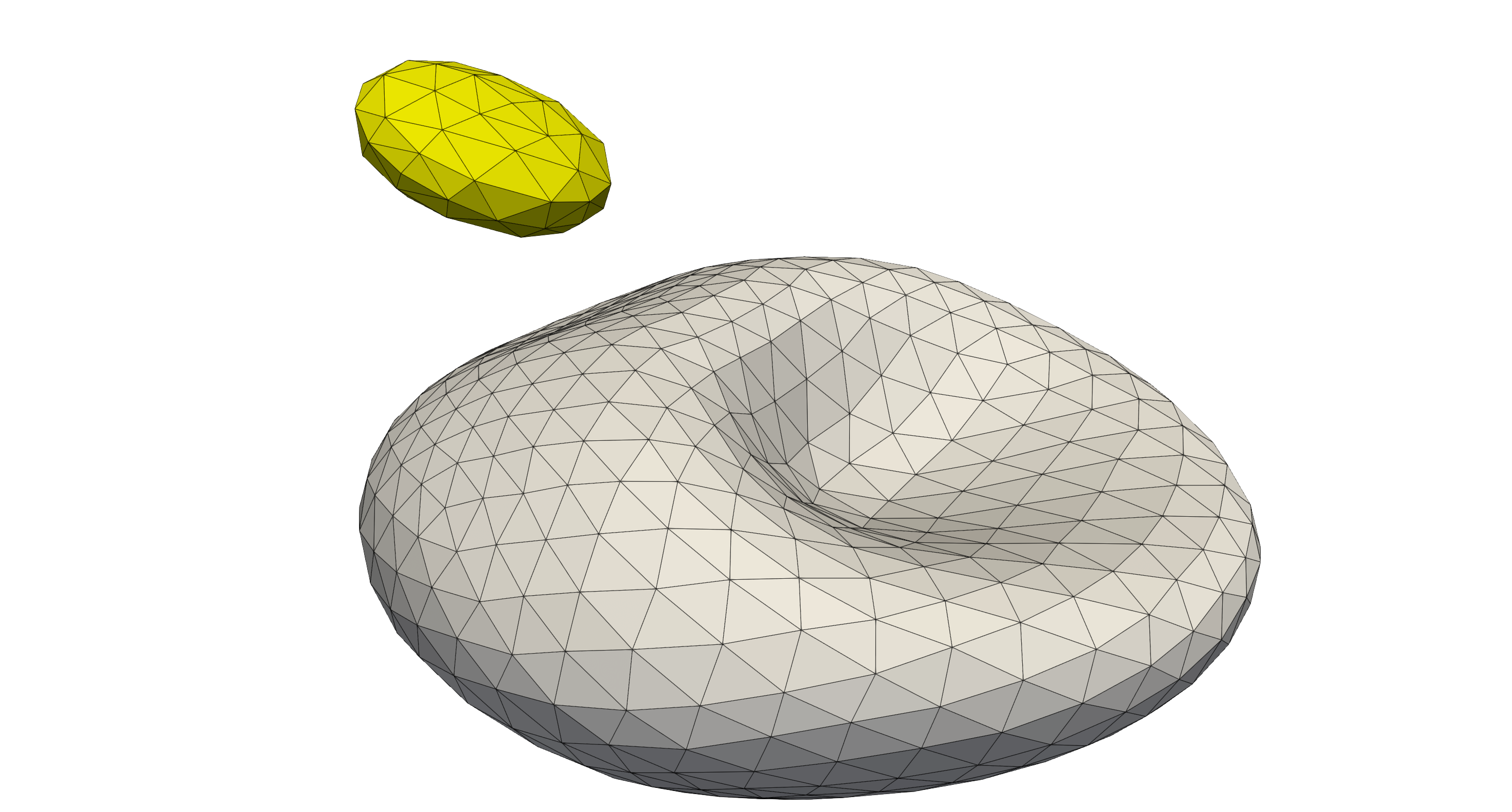
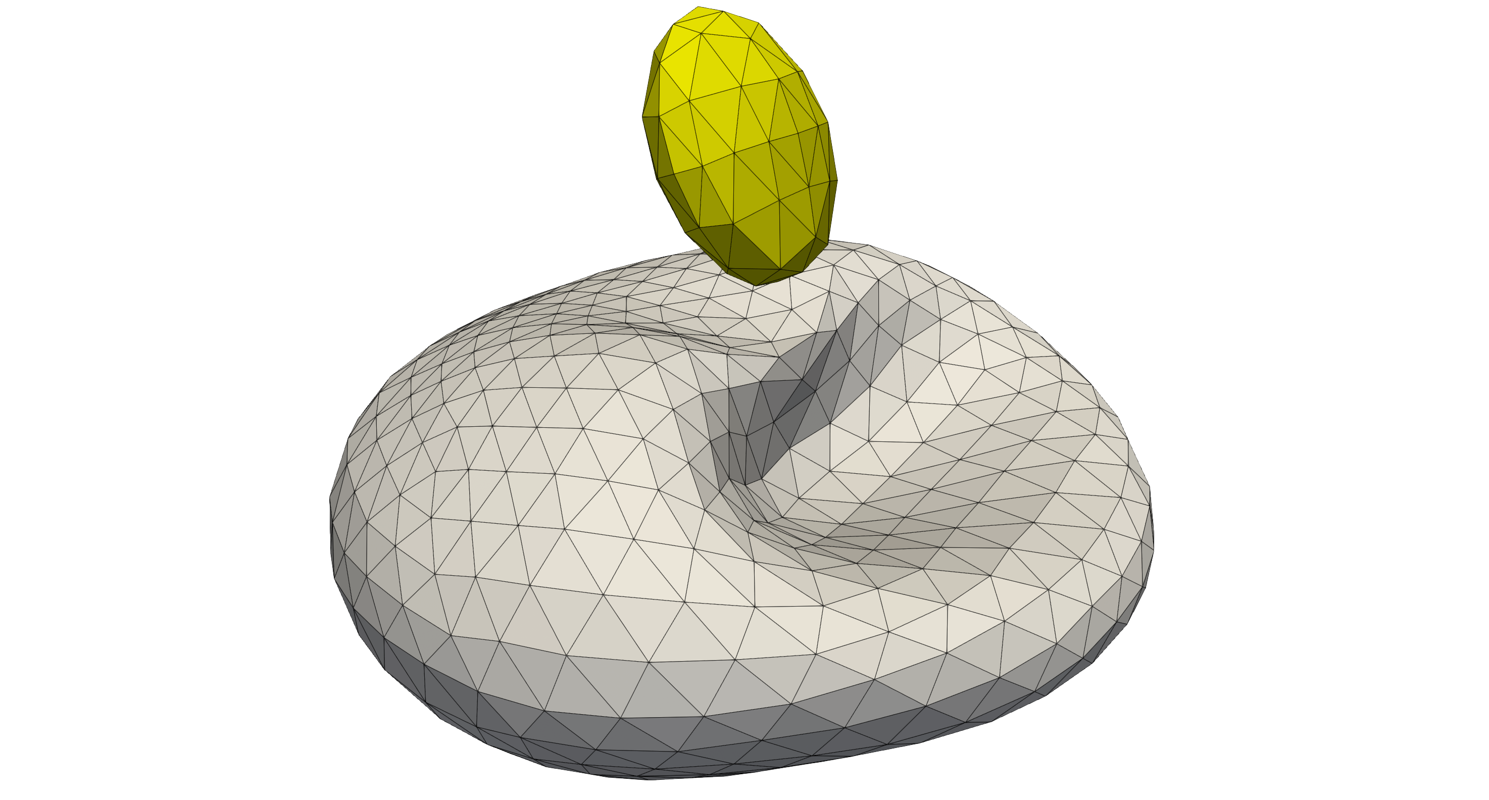
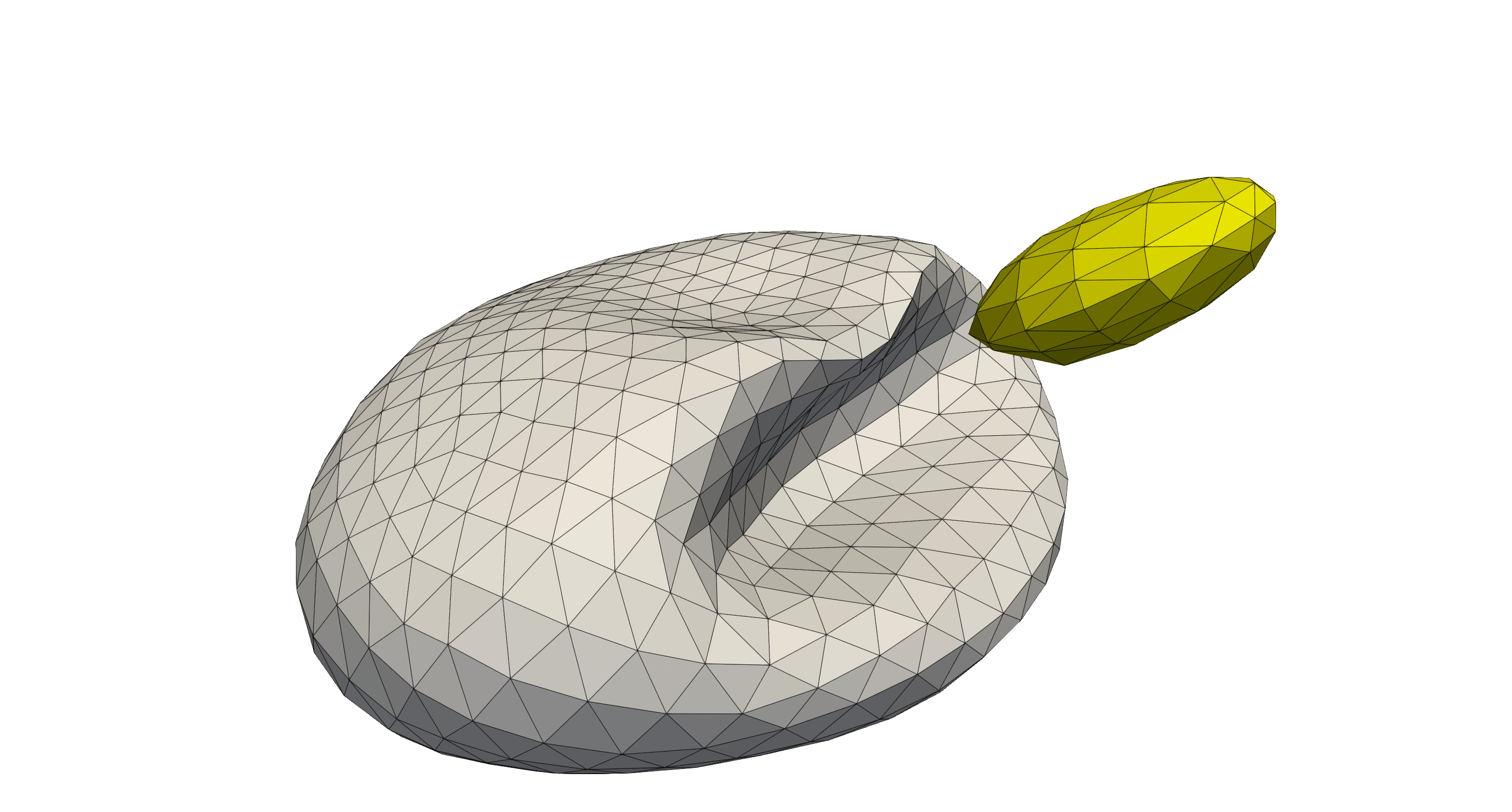
The following RBC-PLT interaction is observed, where the PLT passes besides the RBC and clearly showing the interaction between both cells. Note, both cells are immersed within a shear flow, so there is the tendency for the cells to rotate around their own axis. To ensure the (near) collision occurs, the platelet is slightly offset in the shear flow, such that a larger horizontal velocity is achieved.

The PLT approaching the RBC in the shear flow.

The PLT passing around the RBC in the shear flow where the interaction between both cells is clearly visible by the deformations at the topside of the RBC.

The PLT downstream of the RBC in the shear flow. The effect of the (near) collision is still visible in the current deformations of the RBC.
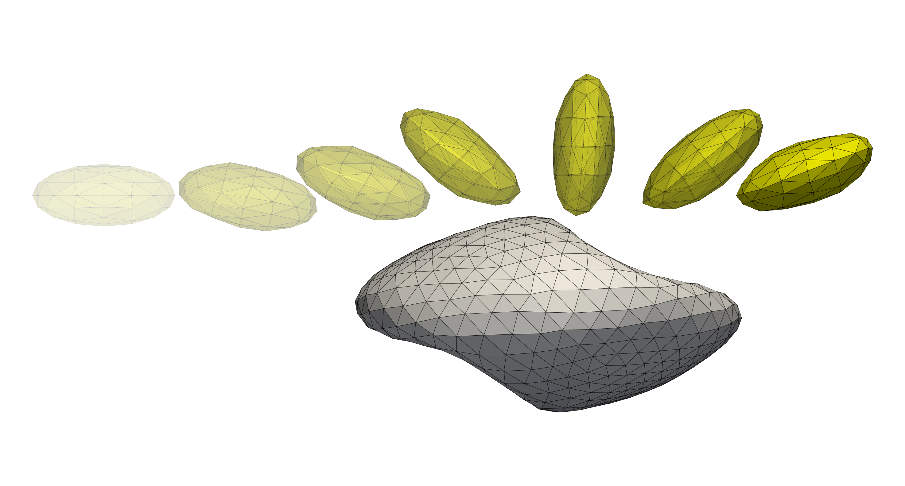
To visualise the path of the platelet, we aggregate various time steps together making it clear how the platelet approaches and moves past the RBC.

The trajectory of the PLT as it passes and interacts with the RBC in the shear flow. The previous positions of the platelet are illustrated with slight opacity.
Initial cell positioning
The initial cell positions are given through *.pos files in HemoCell.
The RBC and PLT cells are respectively given in RBC.pos and PLT.pos.
These files hold the initial position in x, y, z coordinates and the three
rotations around the corresponding axis. The initial conditions can be modified
to observe different collision interactions between both cells.
The files start with a header indicating the number of cells present in the file, followed by a position and rotation for each file in the subsequent lines, e.g.
# RBC.pos
1
5.5 13.0 7.0 90.0 0.0 0.0
Configuration
In addition to the RBC and PLT positions, there are three main configuration parameters to consider in this example:
<domain><shearrate>: this controls the shear rate int he domain and is presented uniformly by specifying velocity boundary conditions on the top and bottom boundaries of the domain.<sim><interiorViscosity>: the interval at which the interior and exterior fluid cells are determined near the boundary of the cells. If the cells move a lot, this can lead to the interior viscosity leaking to the outside of the domain. However, it should be noted that this behaviour has not been observed.Note
Note, the performance impact is low and the set interval can be kept small.
<sim><interiorViscosityEntireGrid>: the interval at which the interior and exterior fluid of every cell is computed exactly using ray tracing.Note
Note, this is extremely expensive and short intervals should be avoided.
Publication cases
To generate the cases presented in [1] the Generate folder provides
additional details, especially in the provided Generate/README. In this
directory additional scripts are found to generate a variety of initial
conditions for the RBC and PLT and additional runner scripts.
